Introduction
Kubernetes is a powerful container orchestration system that can manage the deployment and operation of containerized applications across clusters of servers. In addition to coordinating container workloads, Kubernetes provides the infrastructure and tools necessary to maintain reliable network connectivity between your applications and services.
The Kubernetes cluster networking documentation states that the basic requirements of a Kubernetes network are:
- all containers can communicate with all other containers without NAT
- all nodes can communicate with all containers (and vice-versa) without NAT
- the IP that a container sees itself as is the same IP that others see it as
In this article we will discuss how Kubernetes satisfies these networking requirements within a cluster: how data moves inside a pod, between pods, and between nodes.
We will also show how a Kubernetes Service can provide a single static IP address and DNS entry for an application, easing communication with services that may be distributed among multiple constantly scaling and shifting pods.
If you are unfamiliar with the terminology of Kubernetes pods and nodes or other basics, our article An Introduction to Kubernetes covers the general architecture and components involved.
Let’s first take a look at the networking situation within a single pod.
If you’re looking for a managed Kubernetes hosting service, check out our simple, managed Kubernetes service built for growth.
Pod Networking
In Kubernetes, a pod is the most basic unit of organization: a group of tightly-coupled containers that are all closely related and perform a single function or service.
Networking-wise, Kubernetes treats pods similar to a traditional virtual machine or a single bare-metal host: each pod receives a single unique IP address, and all containers within the pod share that address and communicate with each other over the lo loopback interface using the localhost hostname. This is achieved by assigning all of the pod’s containers to the same network stack.
This situation should feel familiar to anybody who has deployed multiple services on a single host before the days of containerization. All the services need to use a unique port to listen on, but otherwise communication is uncomplicated and has low overhead.
Pod to Pod Networking
Most Kubernetes clusters will need to deploy multiple pods per node. Pod to pod communication may happen between two pods on the same node, or between two different nodes.
Pod to Pod Communication on One Node
On a single node you can have multiple pods that need to communicate directly with each other. Before we trace the route of a packet between pods, let’s inspect the networking setup of a node. The following diagram provides an overview, which we will walk through in detail:
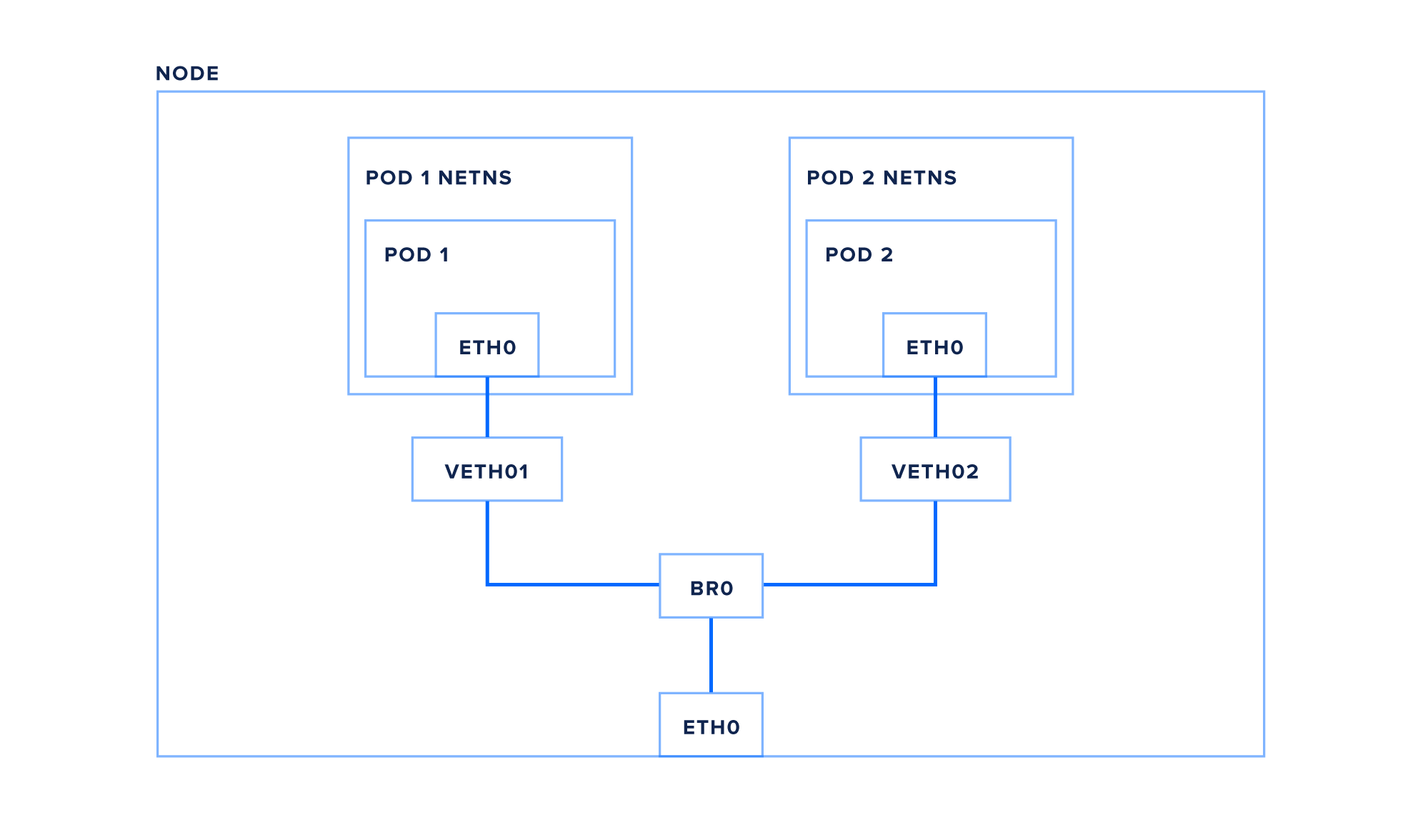
Each node has a network interface – eth0 in this example – attached to the Kubernetes cluster network. This interface sits within the node’s root network namespace. This is the default namespace for networking devices on Linux.
Just as process namespaces enable containers to isolate running applications from each other, network namespaces isolate network devices such as interfaces and bridges. Each pod on a node is assigned its own isolated network namespace.
Pod namespaces are connected back to the root namespace with a virtual ethernet pair, essentially a pipe between the two namespaces with an interface on each end (here we’re using veth1 in the root namespace, and eth0 within the pod).
Finally, the pods are connected to each other and to the node’s eth0 interface via a bridge, br0 (your node may use something like cbr0 or docker0). A bridge essentially works like a physical ethernet switch, using either ARP (address resolution protocol) or IP-based routing to look up other local interfaces to direct traffic to.
Let’s trace a packet from pod1 to pod2 now:
- pod1 creates a packet with pod2’s IP as its destination
- The packet travels over the virtual ethernet pair to the root network namespace
- The packet continues to the bridge br0
- Because the destination pod is on the same node, the bridge sends the packet to pod2’s virtual ethernet pair
- the packet travels through the virtual ethernet pair, into pod2’s network namespace and the pod’s eth0 network interface
Now that we’ve traced a packet from pod to pod within a node, let’s look at how pod traffic travels between nodes.
Pod to Pod Communication Between Two Nodes
Because each pod in a cluster has a unique IP, and every pod can communicate directly with all other pods, a packet moving between pods on two different nodes is very similar to the previous scenario.
Let’s trace a packet from pod1 to pod3, which is on a different node:
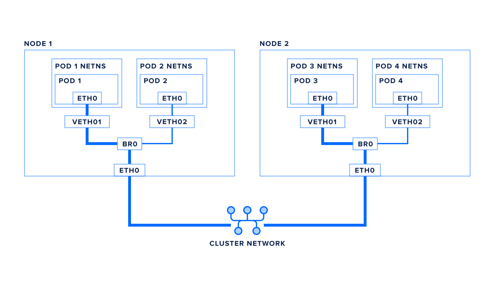
- pod1 creates a packet with pod3’s IP as its destination
- The packet travels over the virtual ethernet pair to the root network namespace
- The packet continues to the bridge br0
- The bridge finds no local interface to route to, so the packet is sent out the default route toward eth0
- Optional: if your cluster requires a network overlay to properly route packets to nodes, the packet may be encapsulated in a VXLAN packet (or other network virtualization technique) before heading to the network. Alternately, the network itself may be set up with the proper static routes, in which case the packet travels to eth0 and out the the network unaltered.
- The packet enters the cluster network and is routed to the correct node.
- The packet enters the destination node on eth0
- Optional: if your packet was encapsulated, it will be de-encapsulated at this point
- The packet continues to the bridge br0
- The bridge routes the packet to the destination pod’s virtual ethernet pair
- The packet passes through the virtual ethernet pair to the pod’s eth0 interface
Now that we are familiar with how packets are routed via pod IP addresses, let’s take a look at Kubernetes services and how they build on top of this infrastructure.
Pod to Service Networking
It would be difficult to send traffic to a particular application using just pod IPs, as the dynamic nature of a Kubernetes cluster means pods can be moved, restarted, upgraded, or scaled in and out of existence. Additionally, some services will have many replicas, so we need some way to load balance between them.
Kubernetes solves this problem with Services. A Service is an API object that maps a single virtual IP (VIP) to a set of pod IPs. Additionally, Kubernetes provides a DNS entry for each service’s name and virtual IP, so services can be easily addressed by name.
The mapping of virtual IPs to pod IPs within the cluster is coordinated by the kube-proxy process on each node. This process sets up either iptables or IPVS to automatically translate VIPs into pod IPs before sending the packet out to the cluster network. Individual connections are tracked so packets can be properly de-translated when they return. IPVS and iptables can both do load balancing of a single service virtual IP into multiple pod IPs, though IPVS has much more flexibility in the load balancing algorithms it can use.
Note: this translation and connection tracking processes happens entirely in the Linux kernel. kube-proxy reads from the Kubernetes API and updates iptables ip IPVS, but it is not in the data path for individual packets. This is more efficient and higher performance than previous versions of kube-proxy, which functioned as a user-land proxy.
Let’s follow the route a packet takes from a pod, pod1 again, to a service, service1:
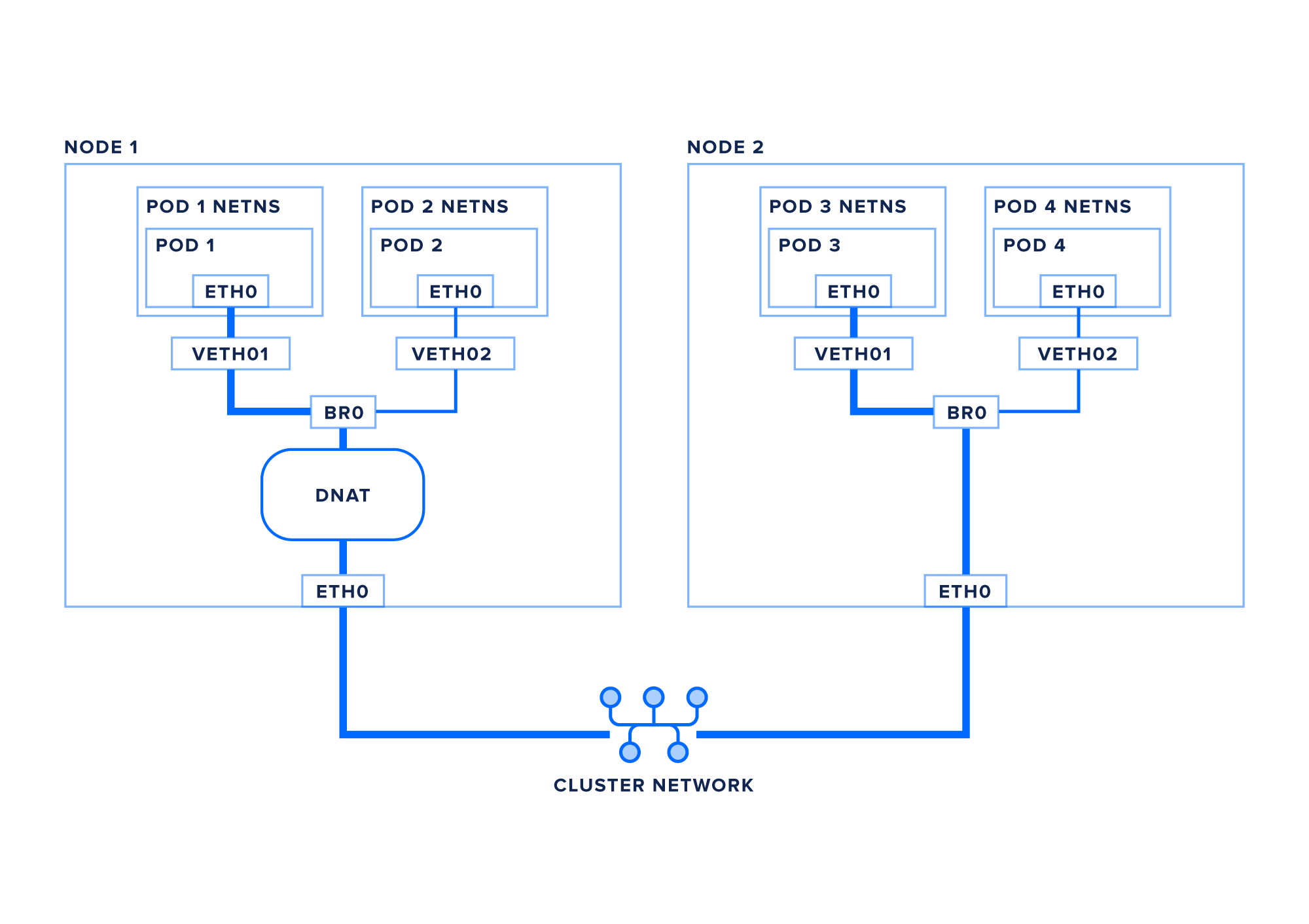
- pod1 creates a packet with service1’s IP as its destination
- The packet travels over the virtual ethernet pair to the root network namespace
- The packet continues to the bridge br0
- The bridge finds no local interface to route the packet to, so the packet is sent out the default route toward eth0
- Iptables or IPVS, set up by
kube-proxy, match the packet’s destination IP and translate it from a virtual IP to one of the service’s pod IPs, using whichever load balancing algorithms are available or specified - Optional: your packet may be encapsulated at this point, as discussed in the previous section
- The packet enters the cluster network and is routed to the correct node.
- The packet enters the destination node on eth0
- Optional: if your packet was encapsulated, it will be de-encapsulated at this point
- The packet continues to the bridge br0
- The packet is sent to the virtual ethernet pair via veth1
- The packet passes through the virtual ethernet pair and enters the pod network namespace via its eth0 network interface
When the packet returns to node1 the VIP to pod IP translation will be reversed, and the packet will be back through the bridge and virtual interface to the correct pod.
Conclusion
In this article we’ve reviewed the internal networking infrastructure of a Kubernetes cluster. We’ve discussed the building blocks that make up the network, and detailed the hop-by-hop journey of packets in different scenarios.
For more information about Kubernetes, take a look at our Kubernetes tutorials tag and the official Kubernetes documentation.
Thanks for learning with the DigitalOcean Community. Check out our offerings for compute, storage, networking, and managed databases.
About the author
Senior Technical Writer at DigitalOcean
Still looking for an answer?
This textbox defaults to using Markdown to format your answer.
You can type !ref in this text area to quickly search our full set of tutorials, documentation & marketplace offerings and insert the link!
 This work is licensed under a Creative Commons Attribution-NonCommercial- ShareAlike 4.0 International License.
Become a contributor for community
Get paid to write technical tutorials and select a tech-focused charity to receive a matching donation.

DigitalOcean Documentation
Full documentation for every DigitalOcean product.

Resources for startups and AI-native businesses
The Wave has everything you need to know about building a business, from raising funding to marketing your product.
The developer cloud
Scale up as you grow — whether you're running one virtual machine or ten thousand.

Start building today
From GPU-powered inference and Kubernetes to managed databases and storage, get everything you need to build, scale, and deploy intelligent applications.